Jaguar Forum banner

Jaguar X300 GUIDE to: Replacing a clock in an X300 (Blue LCD)

1 reading
54K views 33 replies 3 participants last post by  Cestrian  
#1 ·
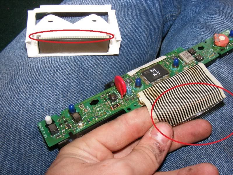
The LCD clock in the X300 is a common problem area, lost 'pixels' and fading display are typical. The root cause of the fault is normally attributed to the ribbon cable which joins the LCD clock panel to the printed circuit board (PCB) itself. You have a few options:

1. Send your unit away and get a refurb (~£100), not very cost effective
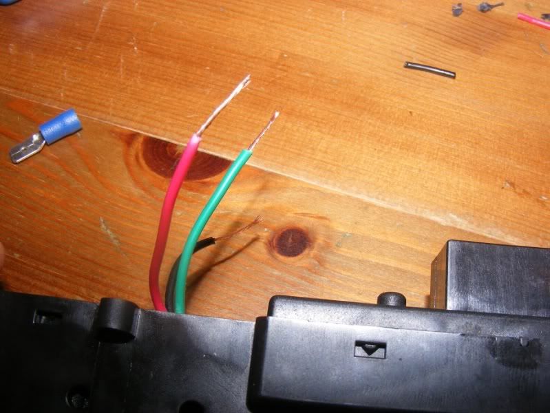
2. Open it up and replace the ribbon cable yourself (~£10), OK if you know what you are doing but it will suffer the same demise eventually
3. Cobble together the existing one by applying pressure to the ribbon cable where it joins the PCB/clock - OK for a quick fix
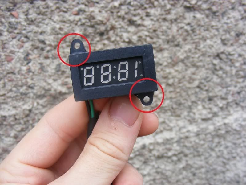
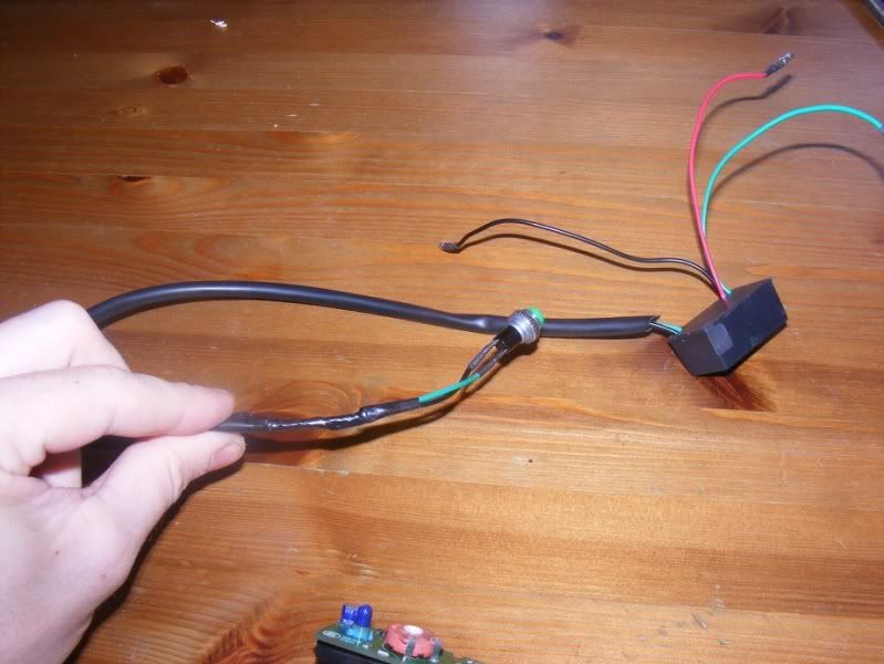
4. Replace the unit for a different kind, this is the route I chose because it is cheap (~£10) and effective for a long term cure

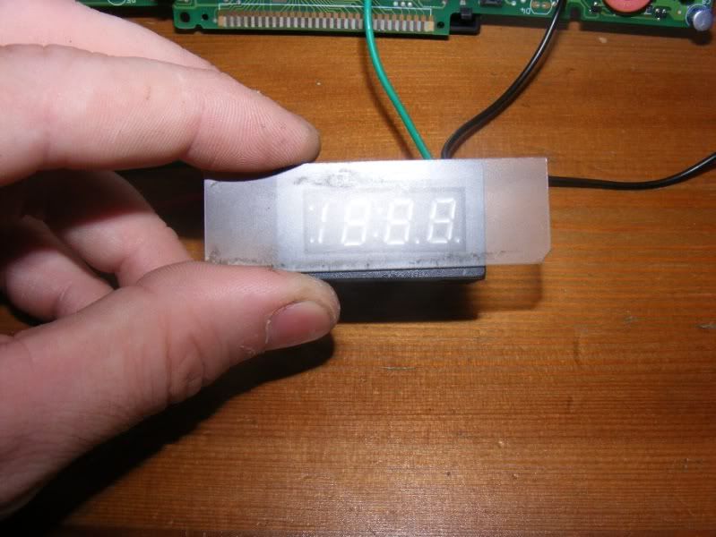
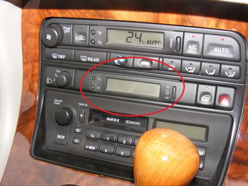
Step 1 - If your clock looks like this then you have a problem! Mine was turned on at this point

Image


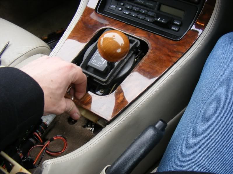
Step 2 - Open the lid of the centre console to expose the first screws we remove

Image


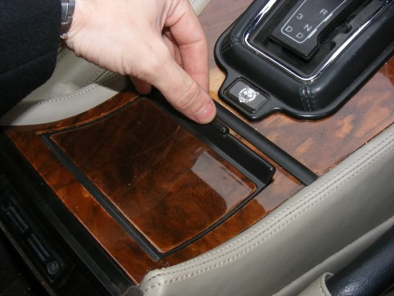
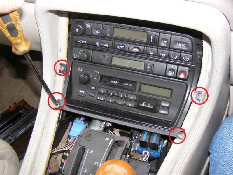
Step 3 - Remove the two posidrive screws (fine threaded) completely

Image

Image
 
#7 ·
Step 11 - Remove the 6 screws holding the stereo etc. in place, note that 5 of my 6 were broken by a previous owner - do not overtigthen them on refitting!

Image

Image


Step 12 - Slide the stereo assembly forwards and unplug the clock multiplug from the back of the unit. Simply depress the tab and pull the cable out (they are a bit stiff)

Image

Image
 
#10 ·
Step 16 - Get a couple of small flatblade screwdrivers. Work around the outside just popping the clips up gently and slide the unit into two parts. Be careful when you pull the two parts away from each other because the LCD will be in one side and PCB on the other

Image

Image

Image


Step 17 - Slide the display out and admire the problematic ribbon cable

Image
 
#11 ·
Step 18 - you can see that a conductive strip glues the ribbon cable to the display and board, this can simply be peeled away (if being replaced rather than squeezed back on)

Image

Image


Step 19 - The LCD screen simply unclips from the mounting bracket and can be removed easily

Image


Step 20 - If only you could solder to the LCD screen you would be able to re-make the 28 connections however you will need to get some special cable to fix these connections. At this stage I decided to go down the path of getting a new LCD screen and eBay revealed a 12V LED clock for £10 delivered from China.

I bought "12V Blue LED Digital Electric Clock For Car Motorcycle" from a seller called topthinkstore, it was 9.99 and took a while to arrive (4 weeks) but is an economical way to go

Image
 
#22 ·
Step 32 - Now, to make a little wiring loom to connect to the car (note you could have just left the wires long but I like having it modular so you can plug different bits in. Cut the spare wire from the switch and terminate one end with a female spade slip as shown then plug it onto the loom from the control box. Split one of the wires in half to make two shorter leads and you have your loom. Finish by fitting a male spade clip to the ends as shown in the final picture. Note I always fit a female spade slip where voltage feeds something and a male spade clip for the consumer device so when you are unplugging things you have no danger of dropping a live wire and shorting something

Image

Image

Image

Image
 
#23 ·
Image


Step 33 - Hook up to a car battery to test everything works (I did this a few times as I was working), 3 wires are as follows:

1. Green = Negative
2. Black = Permanent live (+12V that keeps the time ticking even when the display is off)
3. Red = Switched live (+12V when you want to light the clock up)

Image


Step 34 - Fit the 6 screws to hold the two parts of the assembly together

Image
 
#24 ·
Step 35 - Now we have made our clock, return to the car to wire it in. Start with the standard connector (picture 1), grip and slide the heatshrink back up the loom so you expose more of the wire (pictures 2 and 3).

Image

Image

Image


Step 36 - Find the black wire in the far corner of the loom (circled on the first picture) and cut it about 3 inches from the connector. Strip the wires and twist them together then fit a female spade clip. This is our ground connection so should be connected to the green wire from the clock (simply plug the two spade clips together)

Image
 
#25 ·
Step 37 - Now we will do the switched live - this is a white wire with a red stripe in the loom. This is our switched live and should connect to the red wire from the clock. Again, cut, twist then crimp together (note picture 3 onwards shows the process of splicing a wire but the first two photos show the wire you are using for the switched live)

Image

Image

Image

Image