

Hi Guys, new How-To...
First, the information written in this post is purely THEORETICAL for now, until I or some other forum-member have
confirmed this. But, as I don't have the time in the next couple of weeks to do this on my own headunit I thought of sharing this
information already. (for those that don't know, I have a headunit with some 'water-damage' I used to track this.)
Instead of using High-level input to Low-level output converters this can be used to connect external amplifiers.
DISCLAIMER: I don't take any responsibility if you damage your headunit!
CAUTION: for this mod you have to take out the mainboard, so this is not as simple as the AUX-IN hack.
In one of my previous posts I mentioned 2 chips (ICs) on the mainboard which would be suitable to 'tap-off' the leads
needed to supply an external amplifier with the audio-signa, these are:
So evaluating the mainboard and schematics I have of these 2 chips I've found 4 'leads' we can use to have FrontLeft,
FrontRight, RearLeft and RearRight channels.
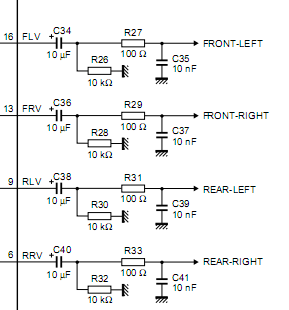
The schematic supplied by NXP suggests that a couple of capacitors and resistors are used before the signal is fed to an
amplifier. Fortunately, Jaguar's designers have followed these suggestions.
Schematic: Somewhere 'behind' the 100-ohm resistor we should 'tap-off' our signal.
![Image]()
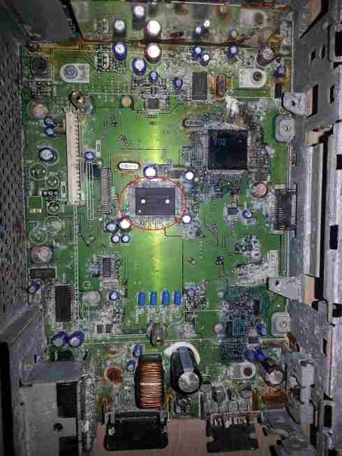
Mainboard (front): after having removed the tape-unit (or cd-unit) the IC we're interested in reveals itself:
![Image]()
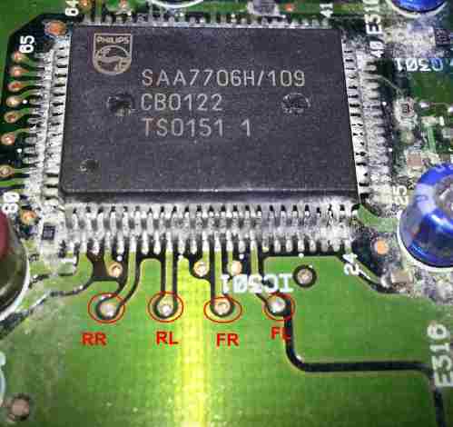
IC: by having a look at the IC (we need pins 6/9/13/16) on the mainboard we can see that these lead to the back of the
mainboard and that the circuit is continued on the back.
![Image]()
Mainboard (backside): after having removed the mainboard from the headunit, we rotate it to the back, so that the
headunit's backside (connectors / aerial) are on the right, while the front (buttons) are on the left.
![Image]()
We can now see 4 seperate lines (for 4 channels) clearly.
Now, solder your signal leads onto these 4 indicated dots,
As ground is a common-ground in this setup, you can take every grounding-point the headunit has. you can even use the
harness.
With these 4 signal-lines you can you what you'd like.
I suggest you solder on 4 female cinch-connectors which are used as an industry-standard. by using this, you can use
standard signal-cables you run to your amp.
To turn on your amp, you can use any accessory-lead your car has. amp will turn on once you put your key to contact.
or (THEORETICAL) use the wire in the connector wich goes to 'OUT-REMO'. In my opinion this is telling the headunit
there's an amp connected, and may even enable the subwoofer settings (as wiring diagram of premium-audio indicates this
is the remote-amp-turn-on-wire).
Cheers!
First, the information written in this post is purely THEORETICAL for now, until I or some other forum-member have
confirmed this. But, as I don't have the time in the next couple of weeks to do this on my own headunit I thought of sharing this
information already. (for those that don't know, I have a headunit with some 'water-damage' I used to track this.)
Instead of using High-level input to Low-level output converters this can be used to connect external amplifiers.
DISCLAIMER: I don't take any responsibility if you damage your headunit!
CAUTION: for this mod you have to take out the mainboard, so this is not as simple as the AUX-IN hack.
In one of my previous posts I mentioned 2 chips (ICs) on the mainboard which would be suitable to 'tap-off' the leads
needed to supply an external amplifier with the audio-signa, these are:
- the 'brain': SA7706H from Philips/NXP, (http://www.nxp.com/documents/data_sheet/SAA7706H.pdf) and
- the 'amp': ST TDA7385 from ST Micro, (HTTP 301 This page has been moved)
So evaluating the mainboard and schematics I have of these 2 chips I've found 4 'leads' we can use to have FrontLeft,
FrontRight, RearLeft and RearRight channels.
The schematic supplied by NXP suggests that a couple of capacitors and resistors are used before the signal is fed to an
amplifier. Fortunately, Jaguar's designers have followed these suggestions.
Schematic: Somewhere 'behind' the 100-ohm resistor we should 'tap-off' our signal.
Mainboard (front): after having removed the tape-unit (or cd-unit) the IC we're interested in reveals itself:
IC: by having a look at the IC (we need pins 6/9/13/16) on the mainboard we can see that these lead to the back of the
mainboard and that the circuit is continued on the back.
Mainboard (backside): after having removed the mainboard from the headunit, we rotate it to the back, so that the
headunit's backside (connectors / aerial) are on the right, while the front (buttons) are on the left.
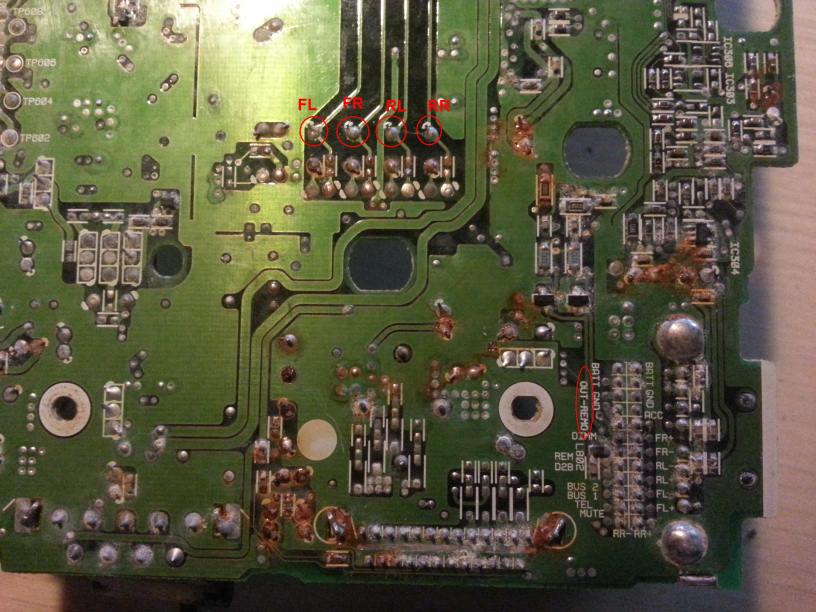
We can now see 4 seperate lines (for 4 channels) clearly.
Now, solder your signal leads onto these 4 indicated dots,
As ground is a common-ground in this setup, you can take every grounding-point the headunit has. you can even use the
harness.
With these 4 signal-lines you can you what you'd like.
I suggest you solder on 4 female cinch-connectors which are used as an industry-standard. by using this, you can use
standard signal-cables you run to your amp.
To turn on your amp, you can use any accessory-lead your car has. amp will turn on once you put your key to contact.
or (THEORETICAL) use the wire in the connector wich goes to 'OUT-REMO'. In my opinion this is telling the headunit
there's an amp connected, and may even enable the subwoofer settings (as wiring diagram of premium-audio indicates this
is the remote-amp-turn-on-wire).
Cheers!