Jaguar Forum banner
21 - 34 of 34 Posts
Discussion starter · #21 ·
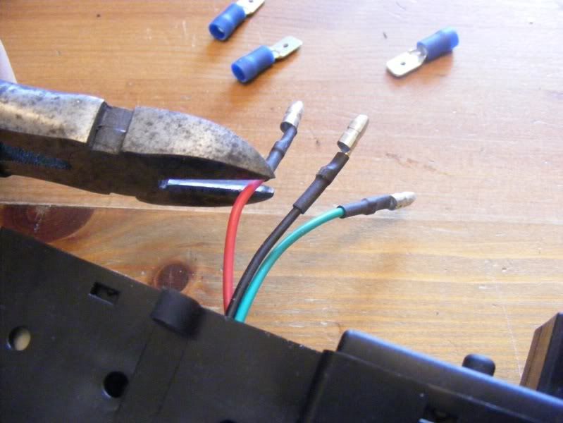
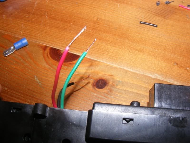
Step 31 - I switched the bullet connectors for spade clips as I had more of these. Simply snip off the old ones (picture 1), strip and twist the wires (picture 2), poke this into a female spade clip (picture 3) and crimp with the tool shown which is much better than pliers (picture 4).

Image

Image

Image

Image
 
Discussion starter · #22 ·
Step 32 - Now, to make a little wiring loom to connect to the car (note you could have just left the wires long but I like having it modular so you can plug different bits in. Cut the spare wire from the switch and terminate one end with a female spade slip as shown then plug it onto the loom from the control box. Split one of the wires in half to make two shorter leads and you have your loom. Finish by fitting a male spade clip to the ends as shown in the final picture. Note I always fit a female spade slip where voltage feeds something and a male spade clip for the consumer device so when you are unplugging things you have no danger of dropping a live wire and shorting something

Image

Image

Image

Image
 
Discussion starter · #23 ·
Image


Step 33 - Hook up to a car battery to test everything works (I did this a few times as I was working), 3 wires are as follows:

1. Green = Negative
2. Black = Permanent live (+12V that keeps the time ticking even when the display is off)
3. Red = Switched live (+12V when you want to light the clock up)

Image


Step 34 - Fit the 6 screws to hold the two parts of the assembly together

Image
 
Discussion starter · #24 ·
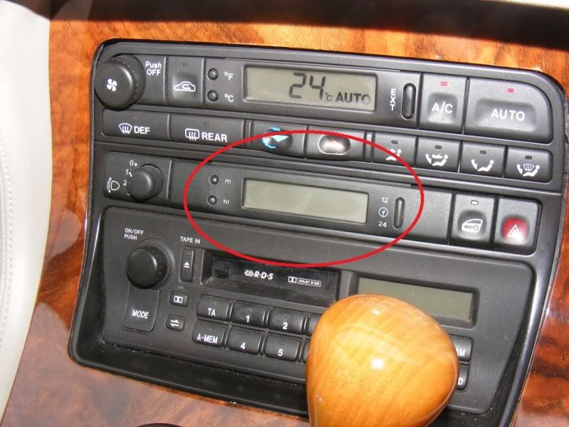
Step 35 - Now we have made our clock, return to the car to wire it in. Start with the standard connector (picture 1), grip and slide the heatshrink back up the loom so you expose more of the wire (pictures 2 and 3).

Image

Image

Image


Step 36 - Find the black wire in the far corner of the loom (circled on the first picture) and cut it about 3 inches from the connector. Strip the wires and twist them together then fit a female spade clip. This is our ground connection so should be connected to the green wire from the clock (simply plug the two spade clips together)

Image
 
Discussion starter · #25 ·
Step 37 - Now we will do the switched live - this is a white wire with a red stripe in the loom. This is our switched live and should connect to the red wire from the clock. Again, cut, twist then crimp together (note picture 3 onwards shows the process of splicing a wire but the first two photos show the wire you are using for the switched live)

Image

Image

Image

Image
 
Discussion starter · #27 ·
Step 38 - Our final connection is the permanent live (connects to the clock black wire). For this we will use the stereo's feed which is at the top left on the white plug to the head unit - it is brown with a grey stripe as shown in the first picture. This is bigger so you have to combine the clock's wire with the stereo's. As usual put the female clip on the line coming in as shown in picture 2. Twist the two wires together (clock black and stereo input brown) as shown in the third picture then connect them all up (picture 4).

Image

Image

Image

Image
 
Discussion starter · #28 ·
Step 39 - Check your wiring, you should have:

1. Clock green wire (ground) going to the black wire on the clock unit loom
2. Clock black wire (permanent live) going to the brown with grey stripe on the stereo loom
3. Clock red wire (switched live) going to the white with red stripe on the clock unit loom

Image


Step 40 - Now slide the clock unit into place and screw it down

Image

Image
 
hi, have just followed J Seaman's really good advice and photos on changing clock in x300, got my motorcycle/car clock from a well known auction site for the grand sum £5.45 post free..the only difference was that I left the time change button on because my soldering skills are not that refined so I have the time change button just at top of ski slope( cannot be seen from seats) but quite a neat place.. thanks J Seaman!!!! regards J Wright...
 
Thank you. I have a new cable and a T tip soldering part on order Can you please add something about how to fix the cable by either removing the old one and replacing it with a new cable or doing something else?.
 
21 - 34 of 34 Posts